Drum Chair Build
Published: 24.01.2025
The beginning
Wanted a simple drum chair and had an itch to do some woodworking after spending the whole summer developing the outline application. Since the ACME threaded rods where quite expensive for the common 32mm diameter used in chairs, I went on to design a simplified version using common hardware store parts and move the adjustment into the feet instead of the base.
As you always do with a simple projects, you spend 4 months creating a custom runtime for executing somewhat obscure JavaScript library, while you slowly go insane and empty all your savings, so you can split the CAD code into multiple files and having automatically export SVG into printable PDFs, but then spend more time fixing issues than actually creating the model. At least there is a BOM that does the heavy lifting of calculating total number of nuts when you have 3 legs and 3 nuts per leg. The answer should be around 9 total.
The app can be found here and the model for this project can be bought on my Ko-fi store.
Model Configuration
- Start with configuring nut and threaded rod. If using inserts for hex nuts, do a test print and adjust settings
- Make sure each part has correct material thickness as they are in real world. They get used for calculating bottom leg width and any inaccuracies will be compounded for each part.
- Adjust tolerances for each part, can be skipped if using traditional woodworking techniques - referencing each part and sanding away until fits.
- Export the 3D models for further CNC operations or PDF templates for hand woodworking. 3D models can be used to get measurements of lengths and dimensions that aren't available in the application at the moment.
- Build the chair - cut threaded rods, assemble hardware inside legs and glue everything.
The Design
The idea was pretty simple. Make a shape for the leg using Bézier curves, then make a circle for the base. Add unnecessary 3D renderings for hardware using whole different CAD language - OpenScad and the BOSL2 library, because I couldn't be bothered to create threaded rods and nuts that don't impact the model besides being a simple lookup table of standard dimensions.
For some reason I was feeling very frugal and didn't want to spend money on square nuts, I added a 3D printable nut insert that was printed on an old bed slinger, that thinks it's located in subarctic temperatures after reaching half way across the Y axis. Would be quite simple to re-solder the bed with a new wire, but the connections at the motherboard have some kind of weird goo that didn't wan't to come off.
Off course my existing M10 nuts where a shorter than the ones specified in the standard, so I just added an offset instead of adding support for thin screws.
On the bright side, using my model I did find a bug in the SVG exporting of Replicad, that got fixed and the world is a better place with a single bug less.
Building process
First leg
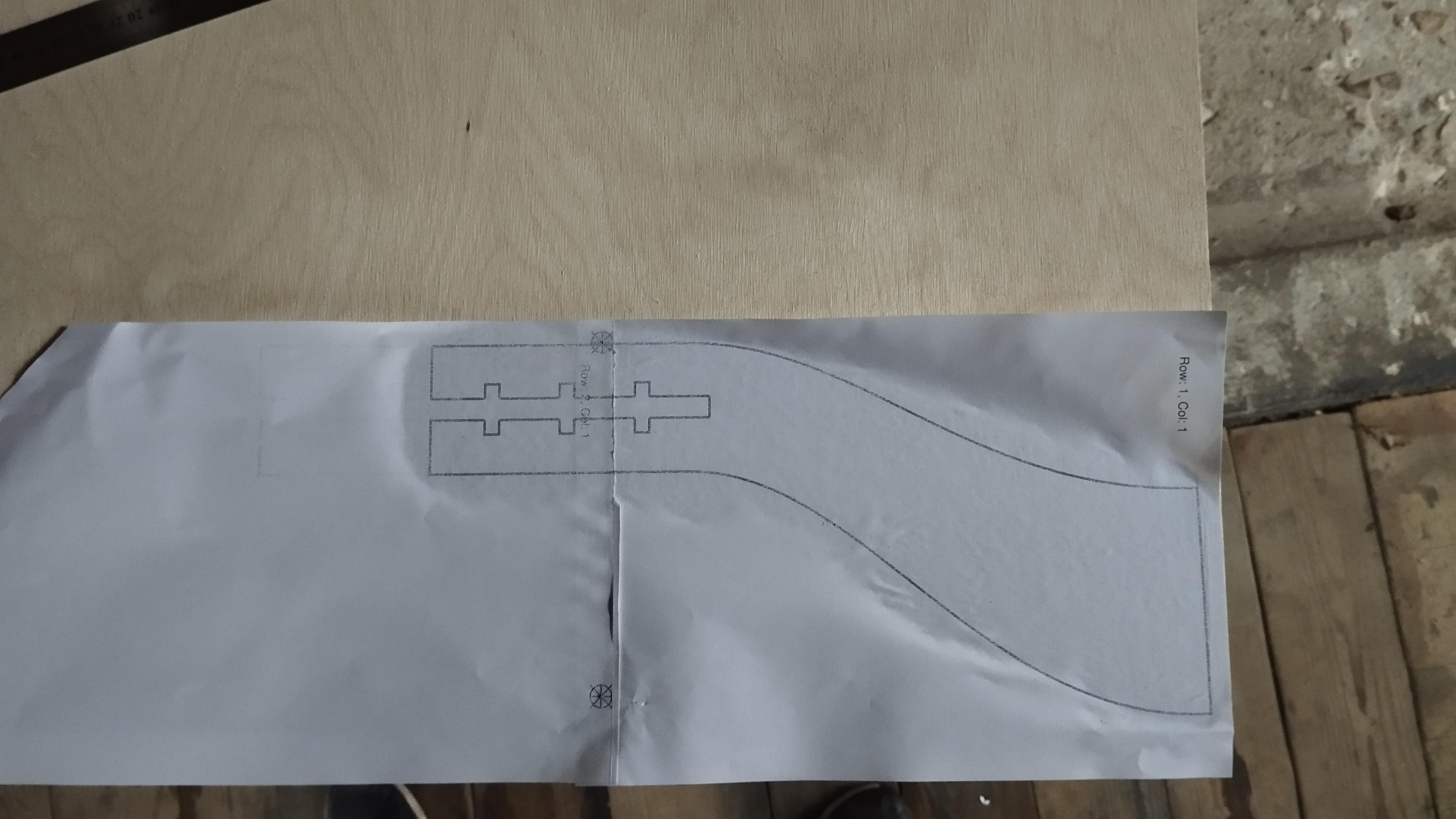
After finally gathering the strength to turn on the printer, that is two whole arms length away, I have successfully printed a template for cutting the legs with the holes for nut inserts and the threaded rod. The initial plan was to use a jig saw and then slightly file to fit it the inserts, but turns out that just gluing on a piece of paper wasn't the most long term accurate solution for keeping straight lines and my chicken legs for arms made it some what time consuming, so I went to town with a rasp and decided that the first leg will be a template with a few dozen tear outs, that will be used as a template for other legs.
Cutting over sized pieces and then creeping up closer with a finer tooth blade, that was laying in my toolbox, was a good idea. Unfortunately, I didn't do it and one of the legs still exhibit quite the tear out for my monkey jigsawing. At least the parts for the threaded rod and inserts will be glued inside and much of my hazardous work won't be seen quite some time, as in never, unless you count the pictures...

Cutting Rest of the Shapes
Did a rough cut of all the shapes with the rough blade and then mounted the jigsaw into a questionable jig, so I can more precisely cut out the shapes with a finer blade. The finer blade is a bit too short, it wobbles around and has some gnarly kickback if going too fast, which is not ideal. Definitely looking at options to get a bandsaw, either make it Matthias Wandel style or buy it, but both of the options require some funds.

At this point, one thing I noticed that the 12mm plywood is not really 12mm and the resulting bottom radius in the template is a larger, but hoped that can be sanded into something resembling a circle. (Spoiler: It was an oval...)
Another thing I thought of after cutting all the shapes, that a washer would be really nice for hex nuts, since the contact area is really small and the nut might eat into the wood. So I kept on brutalizing the plywood leg with a rasp till the hole was sufficient for a nut and washer. Good thing I did all this planning to avoid extra work, right?

To keep up with the great ideas, I realized that the top nut is pretty much useless when the foot is extended. The nuts should have been offset from the bottom instead of using the full length, but now it's too late, at least for this first build. This has been updated in the model.
Insert Holes in Leg Rounding
Did a small pass with a block plane on all the leg roundings to make them somewhat similar to each other. Assigned each rounding part to a leg and marked it with a number. Did a marking with pencil on where the cutout holes should be by placing the leg above.
Did the a bit of sketchy setup by placing two slightly thicker plywood scrap pieces to secure the work piece to the table with a shim and then, as they say, YOLO-ed with router to make a rough cut, while definitely not going over the lines, and then placed the original leg above and chiseled what was left to slide the insert in. Did this on both sides of the leg and each time adjusted the router depth to make the insert fit nicely and the both sides closes without a gap. Then repeated it for each leg - routing and whacking a chisel with a rubber hammer. Should make a wooden mallet to properly call my self a woodworker.


After checking that the thread rod still does the screwing stuff, I glued the smaller outer piece to the larger inner piece. After gluing, placed the pieces back on the leg and a drew a rough circle that would be the corrected radius of the leg rounding. Since I have fucked up the material width in the model, the circle was quite a bit smaller and there was a lot of material that needed to be removed. A bit of chiseling and a lot of planing over two days in the cold, the pieces where somewhat "round" on the bottom, leaving a flat part for clamping. The top was smoothed with a orbital sander. Achieving rounding on the top side might be very hard when they are glue together.
Gluing
Before gluing the rounding to the leg, checked if there is any binding when both sides are clamped. Since at this point it is the easier to fix it, instead of taking the thread in and out a bunch of time to remove material. My perfect measurements and craftsmanship required to do a bit of sanding on one of the side, so the rod doesn't interfere with the sides.
With the theme of great craftsmanship, before gluing everything, I added precision engineered shims made of crumpled pieces of paper in places where I overshoot the sides and next to the washer in hopes that It limits the movement and doesn't slide away when the rod is taken out, making the whole part useless.

This is where I realized I have done goofed again. The rounding wasn't the proper shape and was quite off near the top due the wrong parameters and my "good enough" call when gluing. Did a hell of a lot more chiseling and hand planing in the cold garage to have something that approximates circles at a very large distance. It was far from perfect, but there will be a lot more sanding.
Feet
For my first attempt I cut a very nice half width hole into the pieces that would become the feet. Tried using a thread tap to cut some threads, but that didn't really bite in the shallow hole. Luckily plywood can be tapped using the threaded rod itself and did a few passes to get it nice. Mixed some epoxy and added way to much to the hole, threaded the rod in and left it cure on it's on devices. Everything, expect the over spill of epoxy, looked good until i applied the smallest of perpendicular force to the rod and most of the top layers broke from the plywood.
In the absolute joy of freezing weather I cleaned the rods with a die and made another circular-ish pieces of wood, but this time drilling the hole trough out and repeated the whole epoxy process, including the over usage of epoxy.

Screwed in the feet inside the legs, marked the excess and chipped it away using mostly a rasp and ruing some of the edges. I did try using the jigsaw table jig, but that had so much kickback with the small pieces and the point threaded rod went to my faces while having the added bonus of hastening arthritis. At least I had the great foresight of wearing a large protective mask. After the rough shaping, I sanded with the orbital sander so the oval legs are the same oval as the feet.

Base
Not much here. Used the template to mark the hole ofset and traced out each leg from that. Onwards used freehand routing to get the depth close enough to half and cleaned up with some persuasion from a chisel. At this point in my woodworking career it probably would be wise to make a jig for cutting holes with a router. Added glue, added legs, added clamps and bada bing bada boom the thing was done. Or so I thought until i sat down and there was quite unnerving twist.

Cross Braces
In attempt to not recreate the whole chair with thicker plywood legs, I set out to create braces to help alleviate the twist issue. After spending half a day of modelling and fixing bugs, instead of thinking about where the issue originates, I measured the largest side and angle of resulting model inside FreeCad. (The "calculated values" from models are still in the TODO list.)
I cut the pieces at a resulting 30 degree angle using a jig on a cheap and a bit wonky table saw where the blade is not parallel to the tracks and the angle selection holding plastic is mostly chewed throughout. The resulting braces had a compound angles in two dimensions, which I sanded and planed them way too long for my sanity, since they didn't fit nicely with the other hastily created legs, which have some deviation between the template.

Did this twice and gave up. Added dowels and called it good enough. The twist issue was still noticeable, but a lot more stable. To alleviate the issue fully, the braces needed to join at the narrow parts of the leg, since that's where the most movement occurs.

The future
This chair still needs some sanding and finishing. After that I planned to use some furniture foam and genuine fake leather to cover the base. Stay tuned for a possible part 2 of the build.
